
Anyone who has spent time behind the door of a CNC mill knows that sinking high-depth holes into 316L or 304 stainless steel can turn into an expensive nightmare in seconds. You hear that awful high-pitched squeal, the spindle load meter spikes, and before you can slap the feed hold, your solid carbide drill snaps off 40 millimeters down inside a $3,000 manifold block.
Now you are stuck burning out broken carbide on an EDM sinker or scrapping the part entirely.
When you dig into why these failures happen, nine times out of ten, machinists blame the feed rate, the coolant concentration, or the coating. While those variables matter, the true culprit is almost always tool architecture. Standard jobber drills simply do not possess the right twist drill flute geometry to survive deep hole operations in gummy, work-hardening alloys.
Drilling deep holes—specifically anything beyond 5xD up to 12xD without pecking—demands an uncompromising understanding of how chip formation, torsional shear, and evacuation dynamics intersect inside the flute channel. If you do not tailor your twist drill flute geometry for stainless steel, the metal will seize the tool, pack the gullet, and snap the core.
Here is an unvarnished engineering breakdown of how we design, refine, and deploy high-performance twist drill flute geometry to make stainless steel deep hole machining predictable, repeatable, and fast.
To solve deep hole failure, we have to look directly at the material metallurgy. Austenitic grades like AISI 304 and 316L, as well as duplex grades like 2205 (specified under ASTM A276), present three brutal physical characteristics during hole making:
When you push standard carbide twist drills past 3xD depth in stainless, the chips expand as they curl. The chip volume can easily be three to four times the solid volume of the metal removed.
The Physics of Flute Wedging:
As the chips travel up a conventional 30-degree helix, friction against the flute surface generates secondary heat. The chips expand thermally, wedging tightly between the tool body and the hole wall. Once evacuation resistance exceeds the torsional shear strength of the carbide core, catastrophic snapping occurs.
This is precisely why tailoring your twist drill flute geometry is not an academic exercise—it is the difference between smooth production and a graveyard of broken tools.
The helix angle of the flute acts as the primary conveyor belt for evacuating metal out of the cut.
Traditional drills often utilize a standard 28° to 30° helix angle. While this works fine for general steel or shallow holes, it is a recipe for disaster when drilling stainless steel at 5xD, 8xD, or 10xD depths.
In deep hole stainless applications, we almost universally adjust the twist drill flute geometry toward a fast helix—typically between 34° and 38°.
Helix Angle Evacuation Dynamic:
- Standard Helix (28° to 30°): Slower vertical lift path, high axial thrust resistance, elevated risk of chip packing at depth.
- Fast Parabolic Helix (35° to 38°): Steep vertical lifting vector, low cutting shear resistance, rapid continuous chip evacuation.
However, there is an engineering trade-off that many tool designers ignore: rigidity. As you steepen the helix angle, the torsional stiffness of the drill body naturally decreases. If your twist drill flute geometry does not compensate for this loss of core stiffness, the drill will chatter violently upon hole entry.
To make a fast helix work in tough alloys, you must pair it with specialized web architectures.
The web is the central structural backbone of any drill. If the web is too thick, there is zero room for chips to flow; if it is too thin, the drill snaps under minimal torsional loading.
In high-performance twist drill flute geometry, web design is an uncompromising balancing act governed by cross-sectional area ratios.
Drill Body Cross-Sectional Area Distribution:
Total Tool Section = Core Web Area (Torsional Rigidity) + Flute Gullet Area (Chip Evacuation Space) + Land Margins
Target Ratio for Stainless: Approximately 30% core web area to 70% dynamic flute volume.
For deep hole standard twist drills running in stainless, the web thickness at the point should measure roughly 28% to 32% of the drill diameter (0.28D – 0.32D).
If you drop below 0.25D, the chisel edge flexes, creating hole wandering and massive runout. If you go thicker than 0.35D, the chisel edge creates enormous thrust resistance, generating high localized heat that work-hardens the material right before the main lips engage.
Standard drills typically maintain a constant web thickness throughout their flute length. That is a terrible approach for deep holes.
Superior twist drill flute geometry incorporates both back taper on the outer diameter and web taper along the flute channel:
By engineering the twist drill flute geometry with an expanding flute gullet, the chips experience progressively lower frictional resistance as they travel upward, acting as a natural chip evacuation drill.


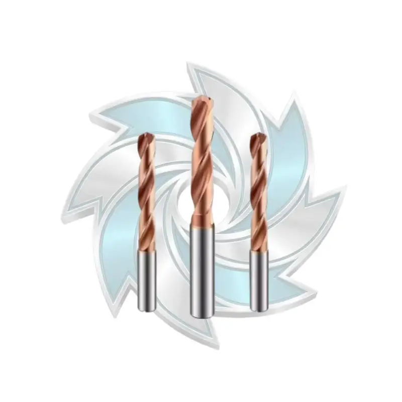
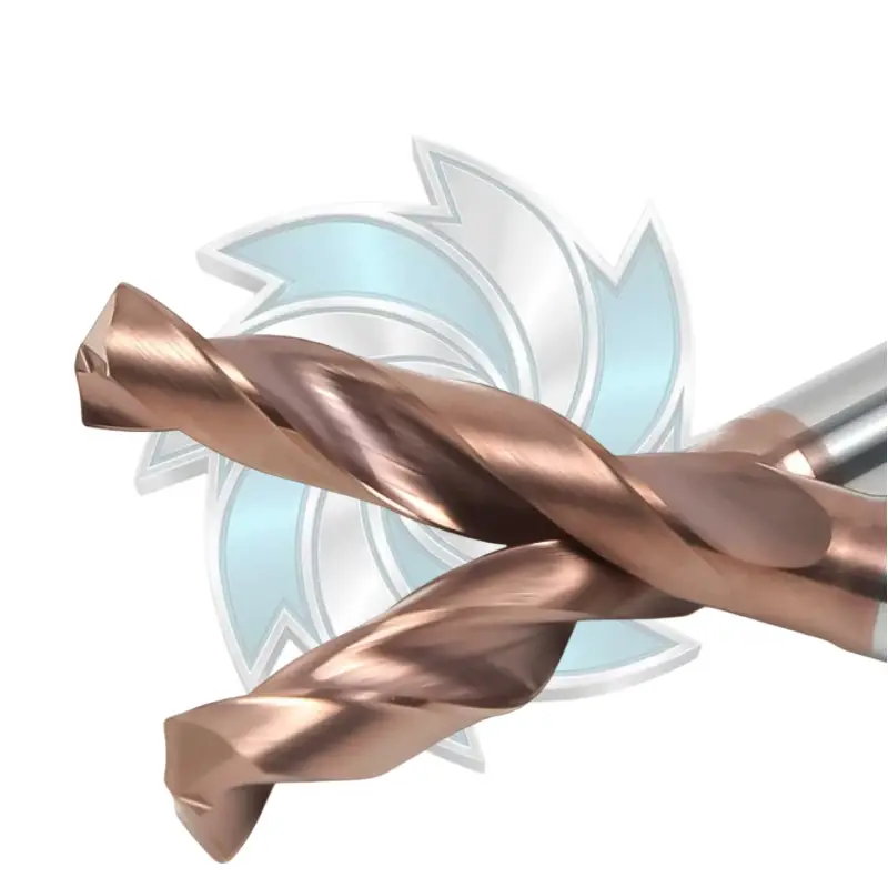
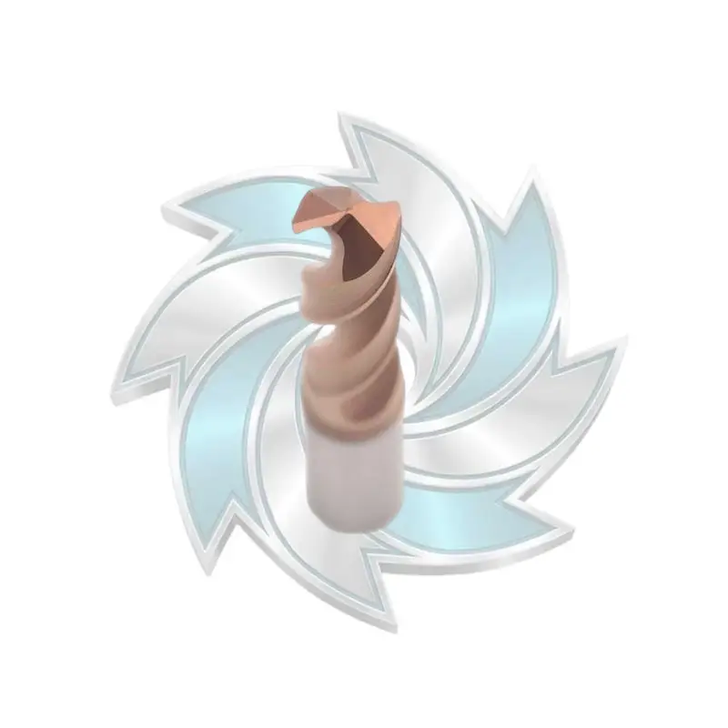
Engineered for precision CNC drilling, our high-performance carbide twist drills deliver exceptional dimensional accuracy across cast iron, structural steel, and stainless steel. Featuring a 140° self-centering point geometry and wear-resistant PVD coating, these industrial carbide twist drills significantly enhance tool life in volume production. Durable Mills supplies premium straight shank carbide twist drills designed to minimize cycle times and machine downtime.
A conventional twist drill flute utilizes a standard circular arc profile. In shallow cuts, this rolls a tight, conical chip. But in deep holes, that tight curl becomes a liability: the chip coils so tightly that it forms a continuous spring, rubbing the walls and generating extreme friction.
For deep hole stainless machining, the circular flute profile should be replaced with an optimized parabolic flute geometry.
Parabolic Flute Advantage:
A parabolic flute profile widens the gullet floor, flattening the bottom curvature and straightening the flute wall. Instead of forcing the chip into a tight, dense spiral, the parabolic twist drill flute geometry encourages an open, loosely folded “C-shaped” or clock-spring chip that clears smoothly without wedging.
When designing this profile, the flute cross-sectional area should occupy at least 50% to 55% of the total tool cross-section at the front of the drill, tapering smoothly toward the back.
This specific twist drill flute geometry allows cutting fluid to enter unimpeded while chips glide out on a high-velocity hydrodynamic fluid cushion.
You cannot guess your way to a reliable tool geometry; you have to run the numbers. When cutting austenitic stainless, the tool must withstand substantial torsional moments caused by both cutting action and chip drag along the flutes.
The mechanical behavior can be modeled using foundational cutting mechanics, as outlined in academic literature like the CIRP Annals manufacturing research.
The torque required to shear the metal at the main cutting lips is expressed as:
Torque Formula:
Mc = (kc1.1 * f^(1 – mc) * D^2) / 8000
Where:
Once you calculate Mc, you must determine whether your twist drill flute geometry can survive that torque without catastrophic shear failure. The maximum torsional shear stress (tau_max) acting on the drill core is calculated as:
Torsional Shear Stress Formula:
tau_max = (16 * Mc) / (pi * d_core^3)
Where:
If your twist drill flute geometry relies on an overly aggressive flute undercut, d_core shrinks. Notice that d_core is raised to the third power: if you reduce the core web diameter by just 20% to gain chip space, you slash the drill’s torsional strength by nearly half (48.8%)!
That is why precision tool grinding must balance flute depth with web thickness to keep tau_max comfortably below the transverse rupture strength (TRS) of your sub-micron carbide grade (which usually sits between 3,800 and 4,400 MPa according to the ISO 513 standard).
Another vital check during flute engineering is the chip expansion ratio:
Chip Packing Ratio:
R_pack = V_chip / V_flute
V_metal = (pi * D^2 / 4) * f * n
Where V_metal is the solid metal removal rate, and V_flute is the open dynamic volume of the flute.
For stainless steel, the expansion factor of deformed serrated chips can reach 3.5. If R_pack inside your twist drill flute geometry approaches 0.85, chip compaction begins, immediately followed by tool seizure. An optimized geometry maintains R_pack under 0.55 during full-depth engagement.
Flute geometry does not stop at the helical channel. The way the flutes intersect the front cutting lips and the outer diameter margins dictates whether you enter the cut cleanly or immediately work-harden the entry surface.
Old-school 118° point angles should be retired when tackling deep stainless holes. A modern twist drill flute geometry for stainless steel demands a 138° to 140° point angle.
A flatter point angle provides three major operational benefits:
The center chisel edge of a conventional drill does not cut; it smashes and extrudes metal through compressive force. In work-hardening alloys, that extrusion creates an ultra-hardened plug right at the center of the hole.
We utilize a modified 4-facet or curved helical split point that cuts straight to the exact center axis. By grinding the web thin right at the point (often down to 0.08D), thrust forces plummet by up to 45%, keeping cutting temperatures cool right from the first revolution.
Many machinists assume double-margin drills are always superior because they provide extra stability. In deep stainless holes, however, that extra margin can be lethal.
A secondary margin that runs continuously from point to shank creates excessive contact area against the hole wall. In austenitic stainless, this rubbing friction work-hardens the hole surface, generates secondary heat, and can weld the tool margin to the bore.
Unless you are chasing extreme aerospace hole straightness with ultra-rigid setups, the ideal twist drill flute geometry for deep stainless uses a narrow single margin with generous secondary clearance relief, or a specialized stepped double margin that only engages the bore wall near the tip.


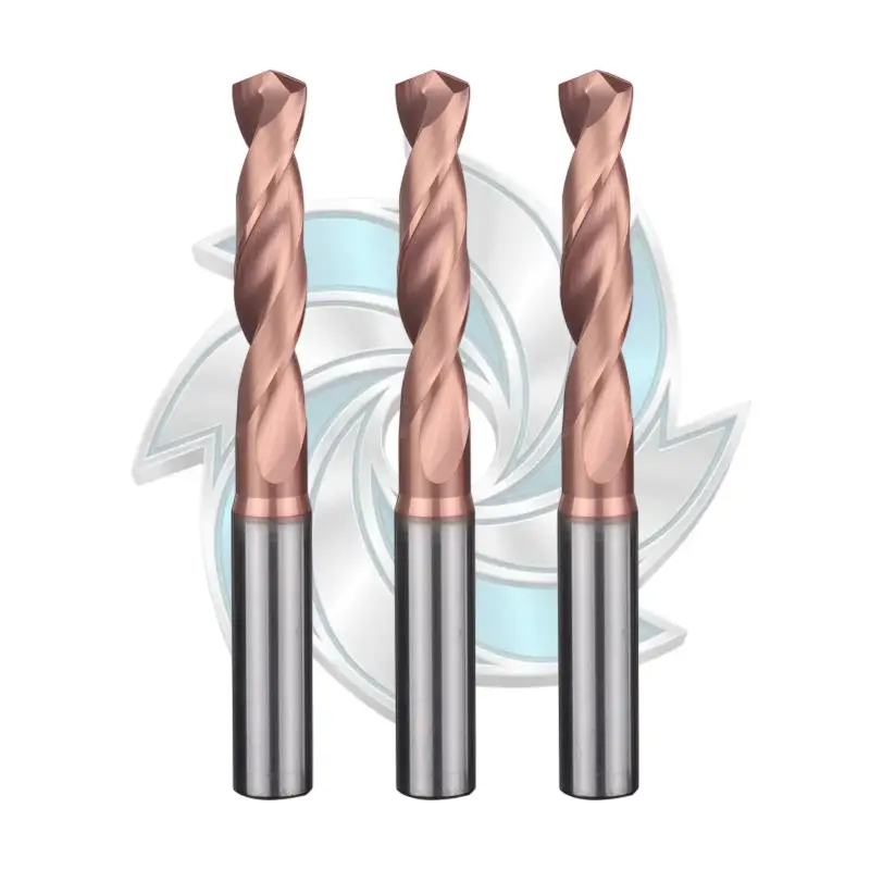
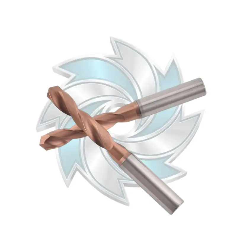
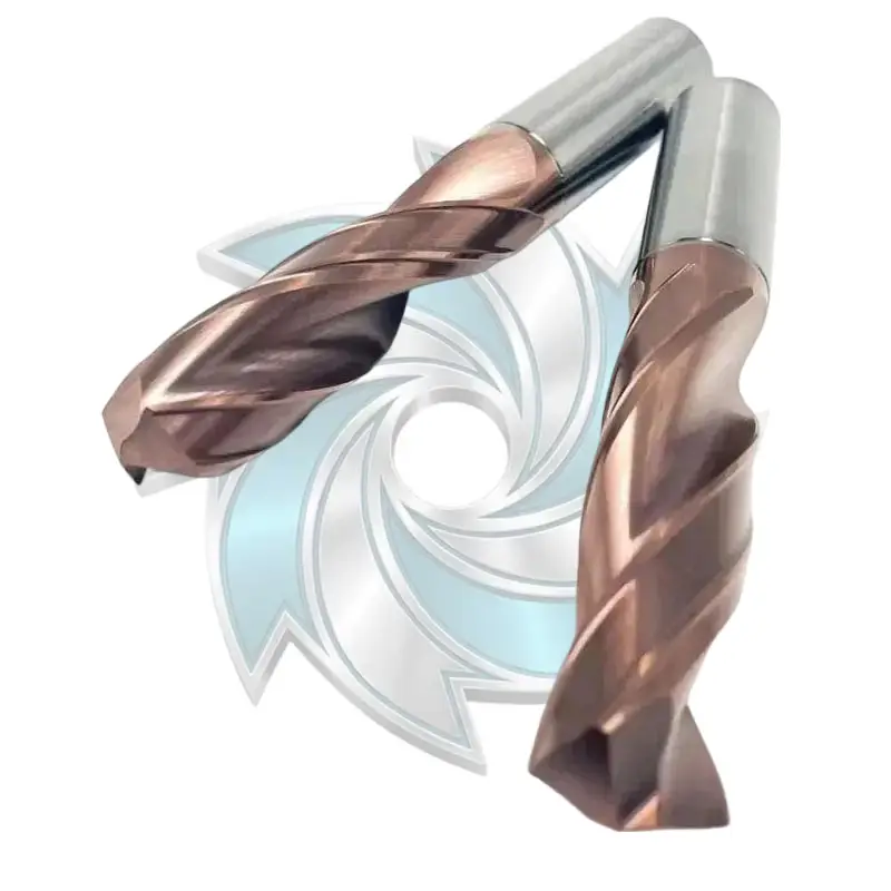
The 5D carbide drill by Durable Mills delivers exceptional centering accuracy and tool rigidity across demanding drilling operations. Engineered for cast iron, stainless steel, and alloy steels, this 5D carbide drill optimizes chip evacuation and heat resistance to increase CNC throughput. Choose our high-precision 5D carbide drill bits for stable hole tolerances and extended production runs.
You cannot discuss twist drill flute geometry without addressing fluid dynamics. In deep hole applications, flood coolant does practically nothing once you pass 3xD depth; the boiling liquid gets pushed out by the rising chips, leading to immediate dry friction.
Through-spindle coolant is mandatory. But the hole placement within the carbide profile makes all the difference.
Internal Coolant Duct Orientation:
Coolant ducts are positioned symmetrically inside the solid carbide core, tracking the exact 37° helix angle. They exit through the secondary flank clearance immediately behind the cutting lips, directing fluid directly into the root of the forming chip.
The internal coolant ducts must be ground to track the precise helix angle of the flute, exiting directly into the clearance face behind the cutting lip.
The coolant must deliver minimum pressures of 40 to 70 bar (600 to 1,000 PSI). High-pressure delivery acts as a hydraulic wedge, snapping chips directly off the tool face and blasting them up the parabolic flutes.
Even the most brilliant twist drill flute geometry will fail if the flute surface looks like a ploughed field under a microscope. Micro-grooves left behind by rough grinding wheels create mechanical anchor points for sticky austenitic chips.
Micro-Finishing Standards:
After grinding, the flute channels must undergo drag finishing or micro-abrasive blasting to achieve a mirror finish with a surface roughness of Ra < 0.1 µm (4 micro-inches).
Polishing minimizes the coefficient of friction between the hot chip and the flute wall. When combined with a high-lubricity PVD coating—such as AlCrN or AlTiN nanocomposites (detailed in machining materials guides by ASM International)—chips glide smoothly out of the hole without sticking.
To see how these geometric elements translate to the spindle, let’s look at an anonymized real-world field test conducted on a horizontal machining center running marine valve manifolds.
We transitioned the customer to a custom-designed twist drill flute geometry for stainless steel manufactured by Durable Mills:
| Machining Metric | Standard Drill (Previous Setup) | Durable Mills Custom Geometry (Optimized) |
|---|---|---|
| Cutting Speed (Vc) | 35 m/min | 65 m/min |
| Spindle Speed (n) | 1,857 RPM | 3,450 RPM |
| Feed per Revolution (fn) | 0.04 mm/rev | 0.09 mm/rev |
| Table Feed (Vf) | 74 mm/min | 310 mm/min |
| Peck Strategy | Peck cycle every 1.5D | Single continuous pass (Zero pecking) |
| Cycle Time per Hole | 42 seconds | 9.3 seconds |
| Tool Life per Grind | 12 to 15 holes | 140+ holes |
By tripling the table feed and running the cut in a single, un-pecked stroke, the custom twist drill flute geometry kept the cutting edge permanently beneath the work-hardened deformation layer.
The fast parabolic flutes cleared clean, tight “comma-shaped” chips directly out through the bushing without any chip compaction. The shop slashed cycle times by 77% while eliminating unexpected tool breakage.
Here is how different drill geometries stack up when faced with deep holes in austenitic and duplex stainless steels:
| Geometric Parameter | Standard Jobber Drill | Standard Parabolic Drill | Durable Mills Deep-Hole Stainless Geometry |
|---|---|---|---|
| Helix Angle | 28° – 30° | 36° – 40° | 35° – 38° Optimized |
| Flute Profile | Circular arc (tight gullet) | Wide parabolic | Modified Wide Parabolic with flat floor |
| Web Thickness at Point | 0.18D – 0.22D (too weak) | 0.35D – 0.40D (too thick) | 0.28D – 0.32D (balanced core) |
| Flute Surface Roughness | As-ground (Ra 0.4 – 0.6 µm) | Ground (Ra 0.2 – 0.4 µm) | Polished Mirror (Ra < 0.1 µm) |
| Point Angle | 118° | 130° – 135° | 138° – 140° High-Shear |
| Split Point Style | Conventional Chisel | Type R Split Point | Micro-Web 4-Facet Self-Centering |
| Coolant Delivery | External Flood | Internal Helical Ducts | Dual Micro-Exit High-Velocity Ducts |
| Max Depth Without Peck | 3xD | 5xD | 8xD – 12xD Continuous |
| Work-Hardening Risk | Extreme (chisel rubs) | Moderate | Minimal (high shear cutting action) |
When a drill goes wrong in the machine, the damaged carbide tells a clear story. Use this troubleshooting guide to identify geometric and operational mismatches:
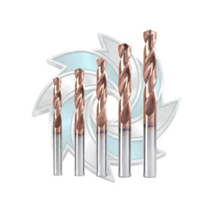


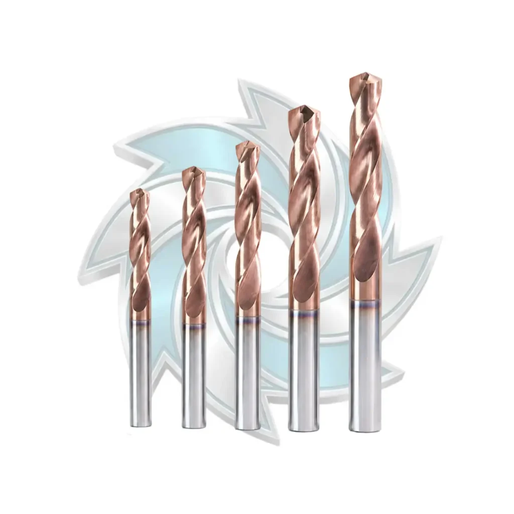
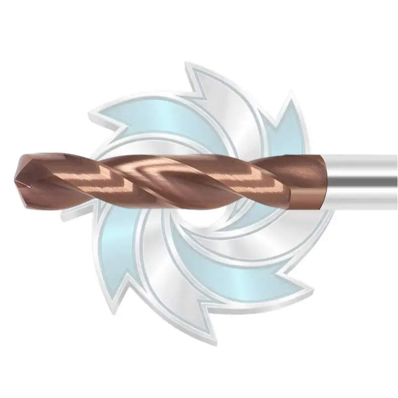
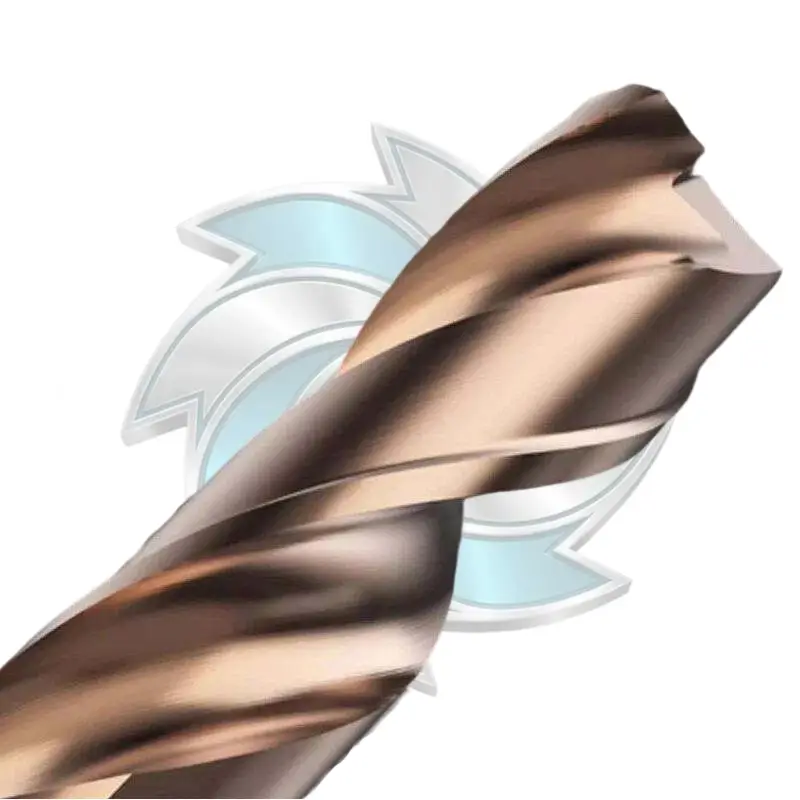
Engineered for high-efficiency holemaking, our solid carbide drill delivers exceptional centering precision across alloy steel and cast iron. This premium solid carbide drill bit features external cooling and an m7 tolerance for smooth chip flow. Choose our solid carbide drills for rigid, high-speed CNC drilling operations.
Generally speaking, avoid pecking whenever possible with modern solid carbide twist drills. Every time the drill retracts, the cutting edges ride over the microscopic glaze at the bottom of the hole. When the tool re-enters, the chisel edge slams directly into work-hardened material, chipping the cutting lips. If chip evacuation forces you to peck, use a high-speed “chip-breaker” micro-peck (retracting only 0.1 mm to 0.5 mm without clearing the hole) rather than a full retract, and never let the tool dwell at the bottom.
With an optimized twist drill flute geometry, dedicated through-coolant (minimum 50 bar), and a rigid machine setup, you can reliably run continuous single-shot drilling up to 8xD to 10xD in 316L and 304 stainless steel. Beyond 10xD, tool deflection and chip-flute friction rise exponentially, often requiring a dedicated pilot hole drilled with a shorter 2xD to 3xD tool featuring a slightly larger point angle (e.g., 142° pilot vs. 140° deep drill).
Breakout failure occurs because the axial cutting thrust suddenly drops to zero while the torsional load remains high. As the drill breaks through the bottom skin, the remaining thin layer of stainless steel deflects elastically, forming a heavy exit burr that grabs the outer corners of the cutting lips. To fix this, drop your feed rate by 50% just 1.0 mm before breakthrough, or select a twist drill flute geometry engineered with corner chamfers to ease the transition through the exit face.
Not necessarily. While AlTiN provides exceptional hot-hardness, high-aluminum coatings can form an aluminum oxide layer that chemically reacts with certain high-nickel stainless grades under extreme friction. Modern AlCrN-based coatings (Aluminum Chromium Nitride) often outperform AlTiN in gummy austenitic steels because they possess a substantially lower coefficient of friction, higher oxidation resistance, and superior adhesion toughness along the honed cutting lip.
Deep hole drilling in austenitic, martensitic, and duplex stainless steels does not have to be an unpredictable guessing game that burns through your tooling budget and slows down your shop floor.
At Durable Mills, we do not believe in generic, one-size-fits-all cutting tools. We engineer, grind, and polish high-performance solid carbide tooling designed specifically to solve your toughest machining bottlenecks:
Explore our full lineup of high-efficiency carbide twist drills and standard-setting standard twist drills engineered for maximum tool life and process reliability.
Have an aggressive deep hole challenge or need custom-engineered flute profiles for your production line? Don’t leave your margins to chance. Reach out to the engineering team at Durable Mills today or drop us a direct email at info@durablemills.com. Let’s review your feeds, speeds, and tool prints together to optimize your cycle times and keep your spindles running at peak efficiency.


