
Walk onto almost any machine shop floor, and you will see it happen sooner or later. An operator loads an expensive pre-hardened 4140 steel manifold block onto a horizontal machining center, dials in the program, and pushes cycle start. Three minutes in, an ear-splitting snap rings out through the enclosure.
A brand-new high-performance solid carbide twist drill just snapped its web right at the entrance of a hole.
When you dig into the scrap bin, you find the culprit: someone grabbed a standard high-speed steel center drill out of a drawer to start the hole instead of an engineered spotting tool.
The debate surrounding a carbide spot drill vs center drill setup is not some academic exercise for tooling designers. For process engineers programming automated lines, selecting a carbide spot drill vs center drill dictates whether you hit tight true position tolerances or scrap high-value castings because your drill walked 0.05 mm off location.
Let’s strip away the textbook fluff and break down the shop-floor physics of a carbide spot drill vs center drill, why certain geometries wreck cutting tools, and how to configure your CNC holemaking operations for maximum tool life and dead-on true position.
To settle the carbide spot drill vs center drill controversy, you have to look at what these two tools were actually designed to do.
A center drill—formally defined under standards like the DIN 333 center drill standard—was created for one specific purpose: cutting 60-degree conical centers in the ends of round stock so a lathe dead center or live center can support the shaft during turning.
Structural Geometry Comparison:
- Center Drill Profile: Fragile cylindrical pilot tip (high break risk under lateral load) leading into a 60-degree flared cone, backed by a thicker secondary shank.
- Carbide Spot Drill Profile: Stubby, ultra-short flute with a heavy reinforced solid carbide core terminating directly in a precision 90-degree, 120-degree, or 142-degree cutting point.
A standard center drill has a stepped design. It features an extremely small, fragile pilot tip followed by a 60-degree flared body. That miniature pilot tip has almost zero web thinning, generates massive thrust loads when plunged into raw metal, and packs chips into its tiny flutes. If you push a center drill into an uneven cast surface or an inclined face on a CNC mill, that delicate pilot bends, deflects, and breaks before the 60-degree flare even touches the workpiece.
A solid carbide spot drill is a completely different animal.
A spot drill features zero pilot tip. It has an ultra-short flute length, a massive web core, and a continuous cutting edge ground to a specific included angle—most commonly 90 degrees, 120 degrees, or 142 degrees. When assessing a carbide spot drill vs center drill, the spot drill acts like a solid pillar of tungsten carbide.
Machinist Rule of Thumb: A center drill is made for lathe tailstocks. A spot drill is built for CNC hole location. Using a center drill to start a high-speed carbide twist drill is like trying to hammer a railroad spike with a glass bottle.
The substrate material also drives the carbide spot drill vs center drill distinction. Center drills are almost always ground from high-speed steel (HSS) or cobalt (M42). HSS has a Young’s modulus of roughly 210 GPa. In contrast, the micrograin substrate in a Durable Mills solid carbide spot drill boasts a Young’s modulus approaching 600 GPa.
That means under identical radial side-loads, a carbide spotter deflects less than one-third as much as an HSS tool. When you evaluate a carbide spot drill vs center drill on a production line where positional accuracy is held to microns, that structural rigidity makes all the difference.
If you take only one piece of advice from this carbide spot drill vs center drill guide, let it be this: never let the included angle of your starter hole be sharper than the included angle of your secondary drill.
Most modern high-performance solid carbide twist drills feature a 140-degree included point angle (or 135 degrees on certain heavy-feed geometries). These drills rely on a self-centering split point, with web thinning engineered to pierce material at the dead center and push chips outward across the cutting lips.
Here is what happens when you enter the carbide spot drill vs center drill angle trap:
When your 140-degree carbide drill enters a pocket created by a 60-degree center drill, the outer corners of the drill make contact with the steep walls of the pocket first. The chisel edge and web are still floating in mid-air.
The outer corners of a drill are its most fragile area, rotating at maximum surface speed (highest SFM) with the least carbide support behind the cutting edge. The drill’s outer lips take the entire axial thrust load of the spindle. The result is catastrophic:
Now, flip the equation in our carbide spot drill vs center drill comparison. You prepare the hole with a 142-degree solid carbide spot drill.
When your 140-degree drill approaches the workpiece, the very tip of its chisel edge touches the bottom center of the 142-degree pocket first. Because 142 degrees is slightly flatter than 140 degrees, the drill engages at its exact point of zero rotational speed.
The chisel edge locates itself perfectly in the dimple. As the spindle feeds downward, the cutting lips progressively engage the material from the center out toward the margins. The outer corners do not touch metal until the entire drill body is fully supported and stabilized by the core.
When comparing a carbide spot drill vs center drill for secondary drill preservation, an angle-matched spot drill eliminates up to 90% of premature cutting edge micro-fractures.
In automated manufacturing, process capability is judged by geometric dimensioning and tolerancing (GD&T). For automated drilling, the governing criterion is True Position, defined rigorously under the ASME Y14.5 dimensioning and tolerancing standard and the international ISO 1101 geometrical tolerancing standard.
True position measures how far the actual center of your drilled hole drifts from its theoretically exact location. The mathematical formula for True Position deviation in a standard Cartesian coordinate system is:
True Position = 2 * SQRT((X_actual – X_nominal)^2 + (Y_actual – Y_nominal)^2)
Understanding True Position Deviation:
- Nominal Center: The exact theoretical coordinate programmed in CAD/CAM (X_nominal, Y_nominal).
- Drift (delta-X, delta-Y): The physical offset of the drilled hole center after tool entry.
- True Position Diameter: Double the radial offset, representing the full diametrical tolerance cylinder around nominal.
Where:
When evaluating a carbide spot drill vs center drill, hole position errors usually stem from dynamic tool deflection during initial contact. A standard twist drill experiences “drill walk.” Because the web of a twist drill does not cut cleanly (it extrudes metal through plastic deformation), it seeks the path of least resistance across surface irregularities.
If you skip spotting or use a wobbly center drill, initial deflection can easily reach 0.03 mm to 0.06 mm. Plug a 0.04 mm radial offset into the formula:
True Position = 2 * SQRT(0.04^2 + 0.03^2) = 2 * SQRT(0.0016 + 0.0009) = 2 * 0.05 = 0.10 mm
If your customer’s drawing calls for a 0.05 mm true position tolerance at Maximum Material Condition (MMC), your part is scrap.
To guarantee that your secondary drill does not walk, the spot diameter must exceed the web thickness of the incoming drill. According to the Industrial Machinery’s Handbook machining guidelines, a twist drill’s web thickness typically ranges between 15% and 20% of its overall diameter.
To calculate the required Z-depth for your spot drill to achieve a target spot diameter, use this trigonometric relationship:
Spot Depth = (Target Spot Diameter / 2) / tan(Included Angle / 2)
Conversely, to calculate the spot diameter produced by a specific programmed Z-depth:
Target Spot Diameter = 2 * Spot Depth * tan(Included Angle / 2)
Let’s run the actual math for two standard spotting tools:
Notice the massive cycle time advantage highlighted by the carbide spot drill vs center drill math. With a 142-degree spotter, you plunge barely a millimeter into the cut to form an ideal centering pocket, saving spindle travel and seconds on every single hole.
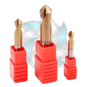


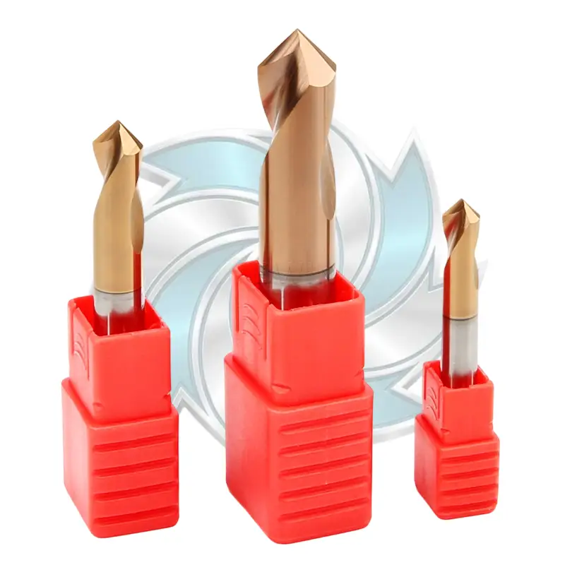
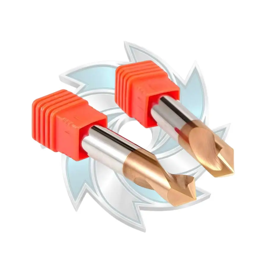
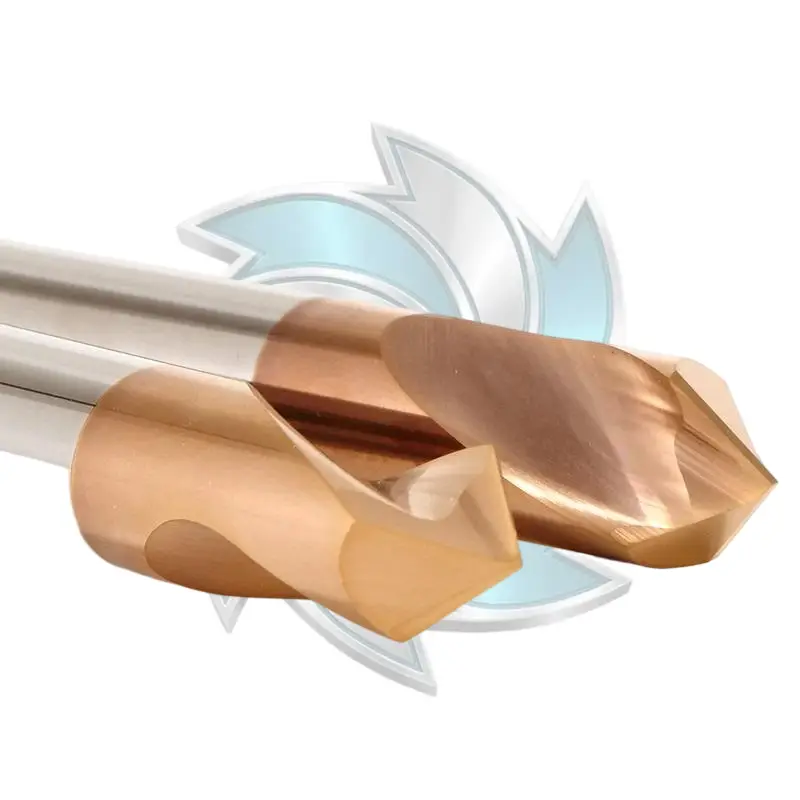
The Solid Carbide Spot Drill delivers exceptional centering accuracy and chamfering efficiency for steels up to HRC55. Engineered for rigid CNC setups, this solid carbide spot drill eliminates tool deflection. Durable Mills manufactures high-durability carbide spot drills for precision B2B machining.
To give automated line programmers a quick reference, here is how the physical properties and cutting behaviors compare across common tooling options:
| Engineering Parameter | Traditional Center Drill (DIN 333 Form A) | 90° Solid Carbide Spot Drill | 142° Solid Carbide Spot Drill |
|---|---|---|---|
| Primary Substrate | High-Speed Steel (HSS) / Cobalt | Sub-micron Solid Carbide | Sub-micron Solid Carbide |
| Modulus of Elasticity (Young’s E) | ~210 GPa (Flexible) | ~580 – 620 GPa (Extremely Rigid) | ~580 – 620 GPa (Extremely Rigid) |
| Point Angle | 60° Cone with Stepped Pilot | 90° Point Angle | 142° Point Angle |
| Chipping Risk to 140° Drills | Extreme (Point angle collision) | Moderate to High (Outer corner strikes) | Zero (Web-first smooth engagement) |
| Deflection Resistance (L/D) | Low (Fragile pilot tip bends) | High (Short stub flutes) | Highest (Minimal depth required) |
| Can Chamfer Hole Entrance? | No (Leaves irregular 60° flare) | Yes (Standard 45° chamfer) | No (Used purely for locating) |
| Cycle Time Efficiency | Poor (Requires slow feed + peck) | Fast | Fastest (Shallow depth needed) |
| Typical True Position (Cpk) | < 1.00 on tough alloys | 1.33 – 1.67 | > 1.67 (Automotive standard) |
When you weigh a carbide spot drill vs center drill across these categories, the center drill loses on nearly every production metric except upfront tool purchase price. But buying a $6 center drill that ruins a $140 carbide drill is a losing trade.
For shops seeking production-ready tooling, the industrial spotting and center drills catalog from Durable Mills provides optimized stub lengths engineered specifically to eliminate spindle runout and tool chatter.
To understand how a carbide spot drill vs center drill transition plays out in real life, let’s examine an anonymized case study from a Tier-1 hydraulic components supplier.
The facility was running ductile cast iron (Grade 65-45-12) valve bodies on a high-speed horizontal machining center cell. Each block required 24 cross-drilled oil galleries using an 8.5 mm solid carbide drill (140-degree point angle) running at 110 m/min surface speed with high-pressure internal coolant.
The original CNC program relied on a standard #4 HSS center drill to spot each hole location.
The shop faced three crippling issues:
Process Capability Benchmark (True Position Cpk):
- Baseline (HSS Center Drill): Cpk = 0.88 (Unstable process, severe drill wander, high scrap).
- Upgraded (142° Solid Carbide Spot Drill): Cpk = 1.74 (Statistically controlled, zero scrap, automotive Six-Sigma compliant).
The manufacturing engineering team conducted an internal carbide spot drill vs center drill performance trial. They pulled the HSS center drill and swapped in a Durable Mills solid carbide spot drill with a 142-degree point angle and TiAlN coating.
Because the spot drill matched the 140-degree twist drill point angle, they modified the toolpath:
The shop ran the carbide spot drill vs center drill comparison over a run of 5,000 valve bodies.
This real-world data demonstrates why the carbide spot drill vs center drill decision is an engineering priority for any high-volume automation line.
If you are transitioning your machine programs from a legacy center drill setup to modern solid carbide spotters, you need to adjust your feeds, speeds, and machine dynamics. You cannot run carbide tooling using HSS program habits.
A spot drill is only as accurate as your toolholder. If your toolholder has 0.015 mm (0.0006″) of runout at the nose, your spot drill will cut an oversized, eccentric crater. When the secondary drill enters an eccentric crater, it immediately walks off-center.
A common habit among manual machinists is adding a dwell (G04) at the bottom of a spotting cycle to “clean up the cone.”
On a CNC mill, never dwell a carbide spot drill in strain-hardening alloys. Materials like 304/316 stainless steel, Inconel, or ductile iron work-harden rapidly. If the spot drill sits at final depth spinning for several revolutions without feeding, it rubs rather than cuts. It creates a work-hardened, glazed layer of metal at the exact point where the secondary twist drill must enter, destroying the next drill’s chisel edge within seconds. Plunge to depth and retract immediately (G81 cycle, never G82).
Many CNC programmers treat spot drilling as a light, fragile cut. They baby the tool with low feeds. But solid carbide tools crave chip load. If your feed per revolution is too light, the cutting edges hone off on the material rather than shearing clean chips.
Consult the Sandvik Coromant drilling engineering guide for base feed rates. For a 10 mm solid carbide spot drill cutting medium carbon steel (AISI 1045), run at least 0.12 mm/rev to 0.20 mm/rev feed. Do not run it at 0.03 mm/rev like an HSS center drill.
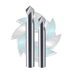


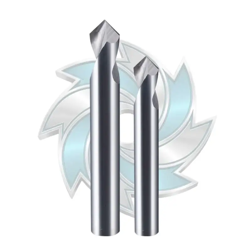
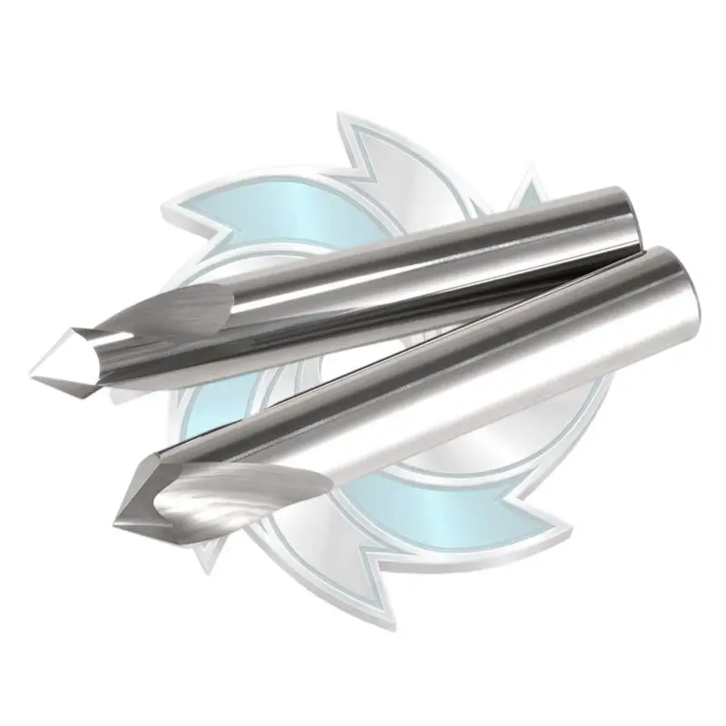
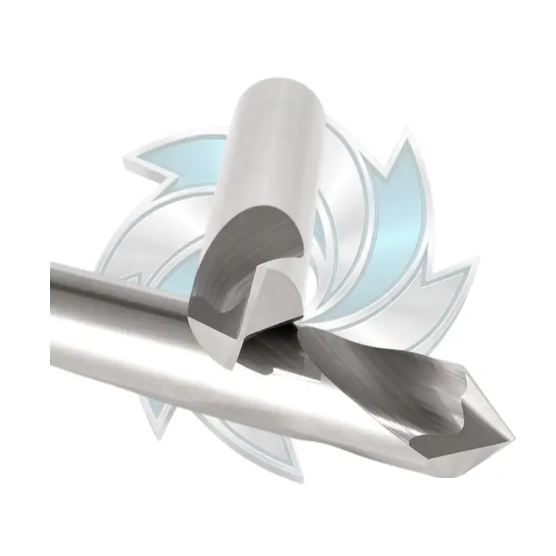
Our high-precision carbide spot drill for aluminum delivers reliable centering accuracy and clean 90-degree chamfering in non-ferrous machining. Manufactured from premium micrograin tungsten carbide, this carbide spot drill for aluminum effectively prevents drill wander and extends subsequent tool life. Upgrade your CNC manufacturing efficiency with high-performance spotting drills from Durable Mills.
To remove any guesswork, here is an operational decision framework:
Yes, but you have to manage a trade-off. Many shops use a 90-degree spot drill programmed deep enough so that the final drilled hole already has a 45-degree deburr chamfer, saving a dedicated chamfering tool change.
However, because the 90-degree spotter creates a steeper pocket than the incoming 140-degree drill, the drill’s outer corners will touch down first. If you choose this path in your carbide spot drill vs center drill planning:
Reduce the incoming twist drill’s initial feed rate by 50% for the first 1.5 mm of travel until the drill is fully engaged.
In difficult materials like titanium, 4140, or duplex stainless steel, skip this compromise. Use a 142-degree spot drill for locating and a dedicated chamfer mill later to prevent outer edge chipping.
That squeal is the sound of torsional chatter caused by point angle mismatch. When a 140-degree drill enters a 60-degree center-drilled pocket, its outer cutting corners strike the steep taper while its web is unsupported in mid-air. This forces the tool to vibrate radially.
Switching your process based on standard carbide spot drill vs center drill best practices—using a 140-degree or 142-degree spotting angle—ensures the web centers first, dampening vibration and eliminating entry chatter entirely.
Modern 3xD and 5xD carbide drills with self-centering point geometries (like DIN 6537 drills) often do not require spotting when drilling into flat, clean surfaces perpendicular to the spindle axis.
However, spotting becomes mandatory when:
1. The entering surface is irregular, cast, crowned, or inclined more than 2 degrees.
2. You are running 8xD, 12xD, or deeper oil-hole drills (which require a 140-degree pilot hole to prevent deep-hole wander).
3. Your customer drawing imposes a true position tolerance of 0.05 mm or tighter, which an unguided twist drill cannot reliably hold across long tool life cycles.
We see this often on shop floors, but it rarely works well. Center drills have narrow flutes and small web dimensions behind their pilots. Grinding off the pilot leaves a tool with irregular cutting relief, no split point, and poor chip evacuation. In a production environment, reground center drills cause erratic tool life and unpredictable true position shifts. Stick to dedicated, ground-from-solid carbide spotters.
Because spot drilling involves shallow plunges, flood coolant often bounces off the tool’s shank due to centrifugal force without reaching the cutting zone. High-pressure through-spindle coolant (TSC) is vastly superior. It flushes away initial micro-chips, preventing chip recutting during entry. Solid carbide spot drills equipped with radial through-coolant channels run up to 40% cooler, prolonging edge sharpness and maintaining hole true position across thousands of cycles.
Holemaking should not be a gamble on your CNC line. When you evaluate the true cost of scrap parts, chipped carbide drill tips, and unnecessary tool changes, the carbide spot drill vs center drill decision becomes crystal clear. Center drills belong on lathe spindles; precision CNC holemaking demands the unyielding rigidity of a solid carbide spot drill.
At Durable Mills, we engineer high-performance holemaking solutions designed to solve tough shop-floor challenges. Our lineup of solid carbide spot drills—available in precision 90°, 120°, and 142° included angles—features ultra-rigid stub designs, micro-grain tungsten carbide substrates, and advanced heat-resistant TiAlN coatings to hold true position across high-volume production runs.
Ready to optimize your automated drilling processes and eliminate drill point fracture?


