
Every machinist running micro-machining jobs knows that sickening feeling. You set up a high-precision cycle, push cycle start on your CNC Swiss lathe or high-speed machining center, and lean in close to hear the cut. Then—silence. Or worse, a microscopic metallic ping. You jog the Z-axis back, pull out your 10x eye loupe, and there it is: a jagged stub stuck right inside the pilot hole.
Dealing with solid carbide micro drill breakage on sub-1.0 mm holes is one of the most frustrating bottlenecks in modern precision manufacturing. When you are drilling holes at 0.5 mm, 0.3 mm, or even 0.1 mm diameters in 316L stainless steel, titanium, or tough nickel alloys, traditional machining intuition stops working. Scaling down a macro drilling process does not work linearly. At the micro scale, physical forces behave completely differently.
If you are fighting recurring solid carbide micro drill breakage on your production floor, the issue is almost never bad luck, and it is rarely a defective batch of carbide. In practical machining, solid carbide micro drill breakage is nearly always driven by two critical variables: unmanaged dynamic runout and mismatched feed parameters.
Let’s cut through the generic handbook advice and explore how to systematically eliminate solid carbide micro drill breakage using rigid workholding, precise drill runout control, and real-world micro hole drilling parameters.
To prevent solid carbide micro drill breakage, you have to appreciate just how fragile these tools are in bending, despite their immense compressive strength and hardness.
Tungsten carbide possesses an extremely high Young’s modulus—typically between 550 and 650 GPa—making it exceptionally rigid. However, that high rigidity comes with ultra-low fracture toughness. Macro drills can tolerate minor deflection, spindle vibration, or slight chip packing by flexing elastically. A micro drill cannot. The moment lateral deflection exceeds elastic deformation limits, catastrophic solid carbide micro drill breakage happens instantaneously.
The resistance of a cylindrical cutting tool to bending deflection depends on its area moment of inertia:
Bending Moment of Inertia Equation:
I = (pi * d^4) / 64Where:
- I = Area moment of inertia (mm^4)
- pi = 3.14159
- d = Effective core or web diameter of the drill (mm)
Notice that fourth power term in the formula. If you halve the diameter of a drill from 1.0 mm down to 0.5 mm, its resistance to bending deflection does not drop by half. It drops by a factor of 16. Drop that diameter further down to 0.25 mm, and the tool is 256 times less rigid than the 1.0 mm tool.
Cantilever Deflection Formula:
delta = (F * L^3) / (3 * E * I)Where:
- delta = Radial tool deflection at the drill tip (mm)
- F = Radial cutting force or side thrust (N)
- L = Free tool overhang or stick-out length (mm)
- E = Elastic modulus of the solid carbide grade (N/mm^2)
- I = Moment of inertia of the drill cross-section (mm^4)
Because tool deflection increases with the cube of length (L^3) and is inversely related to the fourth power of diameter (d^4), even minuscule radial forces trigger severe bending stresses. When radial runout pushes one cutting lip harder into the workpiece than the other, unbalanced lateral cutting forces spike. The tool deflects, flutes bind against the hole wall, and solid carbide micro drill breakage occurs within milliseconds.
If you want to know what causes 80% of premature solid carbide micro drill breakage, look at your toolholder and spindle interface. Runout is the number one cause of sudden tool failure in micro drilling.
In standard macro-machining (say, drilling with an 8.0 mm drill), having 0.010 mm (10 microns) of Total Indicator Reading (TIR) is barely noticeable. On an 8 mm drill, 10 microns of runout represents 0.125% of the tool diameter.
Now, place that exact same 10-micron runout on a 0.30 mm micro drill. That runout now represents 3.3% of the drill diameter. More importantly, it creates an extreme imbalance between the two cutting edges.
Effective Chip Load per Lip Under Runout:
Effective Feed on Lip 1 = Nominal Feed per Lip + Radial Runout
Effective Feed on Lip 2 = Nominal Feed per Lip – Radial Runout
When radial runout approaches your feed per tooth, Lip 1 takes 100% of the cutting load while Lip 2 does not cut at all. Lip 2 simply rubs against the hole wall, generating friction and heat, while Lip 1 experiences massive cyclic shock loads once per revolution. This asymmetric loading initiates micro-cracking at the cutting lip chisel, leading directly to solid carbide micro drill breakage.
On the shop floor, follow one non-negotiable rule to stop solid carbide micro drill breakage:
The Micro Drill Runout Rule:
Total Indicated Runout (TIR) measured at the cutting flutes must never exceed 10% of the drill diameter, and should ideally stay under 0.002 mm (2 microns / 0.00008 inches) for drills under 0.50 mm.
| Drill Diameter (mm) | Max Allowable Runout / TIR (mm) | Target Runout for Long Tool Life (mm) | Primary Failure Mode if Runout Exceeded |
|---|---|---|---|
| 1.00 mm | 0.005 mm (5.0 um) | 0.003 mm (3.0 um) | Chipped corners, oversized holes |
| 0.80 mm | 0.004 mm (4.0 um) | 0.002 mm (2.0 um) | Corner wear, solid carbide micro drill breakage |
| 0.50 mm | 0.003 mm (3.0 um) | 0.0015 mm (1.5 um) | Instant entry snap, solid carbide micro drill breakage |
| 0.30 mm | 0.002 mm (2.0 um) | 0.0010 mm (1.0 um) | Chipping on entry, solid carbide micro drill breakage |
| 0.15 mm | 0.001 mm (1.0 um) | under 0.0008 mm (0.8 um) | Catastrophic solid carbide micro drill breakage |
Many machinists set up a 0.001 mm dial indicator on a tool shank, spin the holder by hand, see zero needle deflection, and assume their setup is rigid. That is static runout.
What actually breaks drills during high-speed machining is dynamic runout. As spindle RPM ramps up to 20,000, 40,000, or 60,000 RPM, centrifugal forces, thermal expansion of spindle bearings, and unbalance within tool clamping systems cause dynamic runout to balloon.
Standard machine tool testing protocols, such as ISO 230-7 for machine tool axes of rotation, document how geometric error motions multiply under high rotational speeds. If your spindle has worn angular contact bearings or grime inside the taper, dynamic runout will easily quadruple at operating RPM, triggering rapid solid carbide micro drill breakage during workpiece contact.


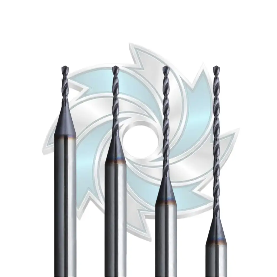
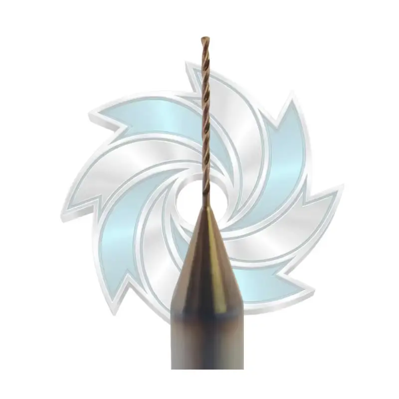
Engineered for high-efficiency deep-hole machining, our high-precision solid carbide micro drill series provides superior self-centering capability and smooth chip clearance. This premium solid carbide micro drill line ensures stable dimensional tolerance across stainless steel, alloy steel, and cast iron. Durable Mills supplies high-wear carbide micro drills for industrial CNC production.
Let’s address an uncomfortable shop reality: standard ER collet chucks conforming to ISO 15488 collet specifications are terrible for micro-hole drilling under 0.8 mm.
A run-of-the-mill ER16 or ER20 collet system has stack-up errors from four distinct interfaces:
When you combine those mechanical tolerances with standard workshop wear, achieving under 0.003 mm runout with standard ER collets is pure luck. To prevent solid carbide micro drill breakage, you need dedicated high-precision micro toolholding solutions:
When paired with purpose-built micro machining tools from Durable Mills, rigid toolholders isolate the carbide blank from chatter, eliminating vibration-induced solid carbide micro drill breakage.
Ask an inexperienced operator how to prevent a small drill from breaking, and their immediate response is: “Slow down the feed rate.”
This intuitive reaction causes extensive solid carbide micro drill breakage. Babying the feed rate is often more destructive to micro drills than pushing them too hard.
Every cutting tool has an edge radius (the hone or natural waterfall prep along the cutting lip). For standard solid carbide micro tools, that edge radius typically measures between 0.001 mm and 0.003 mm.
The Micro-Cutting Boundary Condition:
- When Feed per Tooth (fz) is greater than Minimum Chip Thickness (h_min): The tool shears clean chips cleanly away from the parent material.
- When Feed per Tooth (fz) is less than Minimum Chip Thickness (h_min): The tool cannot cut; it rubs, burnishes, work-hardens the hole bottom, and snaps under friction.
When your programmed feed per revolution (fn) yields a chip thickness smaller than this minimum threshold, the cutting edges cannot bite into the material. Instead of shearing away clean chips, the drill rubs, burnishes the bottom of the hole, generates massive friction heat, and work-hardens alloys like 316L, Inconel, and titanium.
As the machine continues driving the Z-axis downward while no material is being evacuated, axial thrust force spikes exponentially. The carbide flutes buckle, causing sudden solid carbide micro drill breakage.
Always calculate your base cutting variables before running high-aspect-ratio holes to avoid solid carbide micro drill breakage:
Spindle Speed Equation:
RPM = (Vc * 1000) / (pi * D)Feed Rate Equation:
Vf = RPM * fnDefinitions:
- RPM = Spindle rotational speed (rev/min)
- Vc = Cutting surface speed (m/min)
- pi = 3.14159
- D = Drill nominal diameter (mm)
- fn = Feed per revolution (mm/rev)
- Vf = Linear table feed rate (mm/min)
For high-speed micro drilling, cutting data formats and tool definitions standardized under ISO 13399 cutting tool data representation provide accurate baselines for digital tool libraries and CAM programming.
The table below provides production-tested starting parameters for industrial metals. These values are optimized to avoid both edge-rubbing burnish and structural overloading, significantly reducing solid carbide micro drill breakage.
| Material Class | Hardness | Surface Speed Vc (m/min) | Feed fn (% of Drill Diameter) | Example: 0.50 mm Drill RPM | Example: 0.50 mm Feed Vf (mm/min) | Primary Risk Factor for Breakage |
|---|---|---|---|---|---|---|
| Carbon Steel (1045) | 180-220 HB | 45 – 70 | 1.5% – 2.5% (0.008-0.012 mm/rev) | ~35,000 | 280 – 420 | Bird-nesting chips binding flutes |
| Austenitic SS (316L) | 190-230 HB | 25 – 40 | 1.0% – 1.8% (0.005-0.009 mm/rev) | ~20,000 | 100 – 180 | Work hardening; solid carbide micro drill breakage |
| Titanium (Ti-6Al-4V) | 32-36 HRC | 20 – 35 | 0.8% – 1.5% (0.004-0.007 mm/rev) | ~18,000 | 72 – 126 | Heat buildup causing carbide edge chipping |
| Nickel Alloy (Inconel 718) | 38-44 HRC | 12 – 22 | 0.6% – 1.2% (0.003-0.006 mm/rev) | ~11,000 | 33 – 66 | Built-up edge; solid carbide micro drill breakage |
| Brass / Bronze (C36000) | 90-130 HB | 70 – 120 | 2.5% – 4.5% (0.012-0.022 mm/rev) | ~50,000 | 600 – 1,100 | Rapid chip self-feeding grabbing flutes |
| Aluminum (6061-T6) | 95 HB | 80 – 150 | 3.0% – 6.0% (0.015-0.030 mm/rev) | ~60,000 | 900 – 1,800 | Flute packing; solid carbide micro drill breakage |
Note: In cases where your machine spindle cannot reach calculated RPM levels (for instance, maxing out at 15,000 RPM on a 0.3 mm drill), maintain the calculated feed per revolution (fn). Dropping feed alongside RPM keeps you above minimum chip thickness, preventing rubbing-induced solid carbide micro drill breakage.
Standard CNC controls feature two universal peck drilling cycles:
Both of these canned cycles can create severe problems when micro drilling.
Using G73 in deep micro holes (depths > 3x diameter) causes solid carbide micro drill breakage because micro chips do not evacuate simply from an axial pause. Carbide flutes pack tight with swarf, cutting pressure spikes, and the drill breaks on the next forward move.
Conversely, running a standard G83 full retract cycle causes solid carbide micro drill breakage on re-entry. When a 0.3 mm drill pulls completely out of a hole at rapid speed, fine chips suspended in the coolant wash right back into the hole bottom.
When the drill returns at rapid feed (G00) and stops a mere 0.5 mm or 0.2 mm above the previous cut, it can smash into loose chips. Because the tool enters at thousands of RPM under axis deceleration, that mechanical impact creates shockwaves through the drill tip, leading to solid carbide micro drill breakage.
Recommended Custom Micro-Pecking Procedure:
- Rapid advance to clearance plane (Z +1.0 mm).
- Drill pilot hole to 1.5x D depth without pecking.
- Execute primary deep drilling with a progressive peck schedule (D1 = 1.0x D, D2 = 0.8x D, D3 = 0.5x D).
- Retract to an intermediate clearance point inside the hole to keep flutes supported.
- Decelerate feed to 50% on re-entry before touching the bottom of the previous cut.
As hole depth increases, friction along the drill lands increases, and chip evacuation paths become narrower. Fixed pecking depths (e.g., 0.2 mm every peck down to 5.0 mm depth) frequently trigger solid carbide micro drill breakage past 5x D.
Use a progressive pecking schedule:
Shorter pecks at greater depths prevent chip packing, which is a major contributor to solid carbide micro drill breakage in difficult materials.


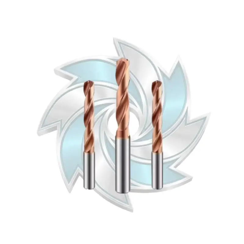
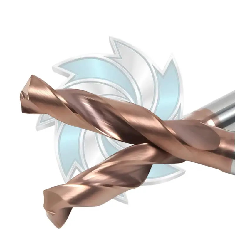
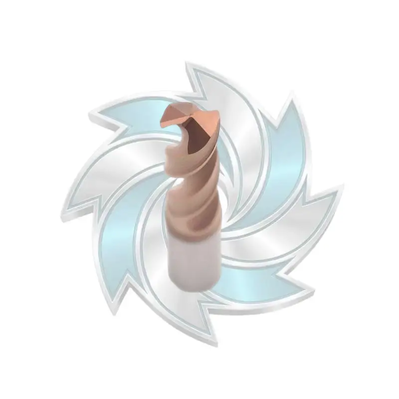
Engineered for precision CNC drilling, our high-performance carbide twist drills deliver exceptional dimensional accuracy across cast iron, structural steel, and stainless steel. Featuring a 140° self-centering point geometry and wear-resistant PVD coating, these industrial carbide twist drills significantly enhance tool life in volume production. Durable Mills supplies premium straight shank carbide twist drills designed to minimize cycle times and machine downtime.
Never plunge a long micro drill (flute lengths > 5x D) directly onto a raw, un-machined surface. Drill runout, slight workpiece surface waviness, or material grain boundaries will cause the drill tip to walk off center. Because solid carbide does not flex, drill walking results in immediate solid carbide micro drill breakage at the margin corners.
Pilot Hole Best-Practice Protocol:
- Face the workpiece first to create a perfectly flat, perpendicular surface.
- Use a short, rigid pilot drill (1x D to 2x D flute length) with a point angle matched to or slightly larger than the primary drill (e.g., primary drill = 135 degrees, pilot drill = 140 degrees).
- Drill the pilot to a depth of 1.0x to 1.5x diameter.
- Enter the pilot hole with the primary drill at low RPM (500 to 1,000 RPM) without feed.
- Ramp up to full cutting RPM and feed smoothly once guided inside the pilot pocket.
Using a pilot drill with a slightly larger point angle ensures the cutting tips of the primary drill engage the material center first. If your pilot has an acute angle (e.g., 90 or 118 degrees), the delicate outer corners of your 135-degree primary drill make contact first, introducing radial chatter and initiating solid carbide micro drill breakage before full engagement.
For high-aspect applications, pairing a dedicated pilot tool with a high-precision Solid Carbide Micro Drill creates stable process conditions that prevent solid carbide micro drill breakage across production shifts.
Carbide drills generate significant cutting zone heat. With micro-sized tools, the volume of material around the cutting flutes is tiny, making heat dissipation very slow.
Without proper cooling, thermal expansion causes the drill body to swell inside the hole. The margins bind against the hole wall, leading to friction welding and rapid solid carbide micro drill breakage.
Coolant Pressure Thresholds for Micro Drills:
- Hole Depth under 3x D: External flood coolant directed via dual micro-nozzles at 5 to 10 bar.
- Hole Depth between 3x and 8x D: Through-tool or focused jet coolant at 20 to 40 bar.
- Hole Depth over 8x D: High-pressure through-spindle coolant (TSC) at 40 to 70+ bar (600 to 1,000+ PSI).
Standard CNC coolant filtration systems rely on 20- to 50-micron filter bags or mesh screens. That is fine for standard end mills, but it is dangerous for micro drilling.
If you are drilling 0.20 mm (200 microns) holes with flutes that have a clearance gap of 20 microns, a single 30-micron metal chip recycled through your coolant tank and sprayed back through the nozzles can wedge between the rotating flute and the hole wall. That wedged particle creates an instant mechanical stop, causing immediate solid carbide micro drill breakage.
For micro hole drilling:
To understand how these variables interact in practice, look at a real-world troubleshooting case from a medical contract manufacturing facility.
The shop was running a high-volume surgical component requiring four 0.35 mm blind lubrication ports drilled 2.8 mm deep (an 8x D aspect ratio) into annealed 316L stainless steel.
The machine was a high-end CNC Swiss-type lathe equipped with an auxiliary 24,000 RPM high-frequency spindle. The operators were experiencing consistent solid carbide micro drill breakage:
A tooling engineer evaluated the setup and uncovered three underlying issues:
When solid carbide micro drill breakage occurs, inspecting the broken tool tip under a microscope provides clear evidence of what went wrong:
| Broken Tool Appearance | Probable Failure Mechanism | Actionable Solution to Stop Breakage |
|---|---|---|
| Clean snap across drill shank or transition neck | Excessive lateral deflection caused by high runout | Verify collet taper cleanliness; measure dynamic runout; maintain TIR under 0.002 mm. |
| Outer cutting corners chipped or sheared off | Shock impact on entry; incorrect pilot hole angle | Match pilot angle to 135-140 degrees; slow down Z-axis entry feed right before contact. |
| Flutes twisted or spiraled before shearing off | Flute chip packing; insufficient pecking frequency | Shorten peck depth; increase coolant wash pressure; check for chip re-cutting. |
| Melted material or built-up edge welded to margins | Thermal starvation; rubbing due to low feed | Increase feed per rev (fn); check coolant filtration and concentration levels. |
| Drill tip walked off-center; curved hole entry | Non-flat workpiece surface; no pilot drill used | Face surface flat; use a rigid stub pilot drill prior to using the deep-hole micro drill. |
| Breakage occurs during rapid retraction | Chip packing in flutes binding on hole withdrawal | Ensure dwell at bottom is zero; retract with active spindle rotation; avoid rapid drag. |
Keep this shop-floor checklist near your machines to prevent solid carbide micro drill breakage:


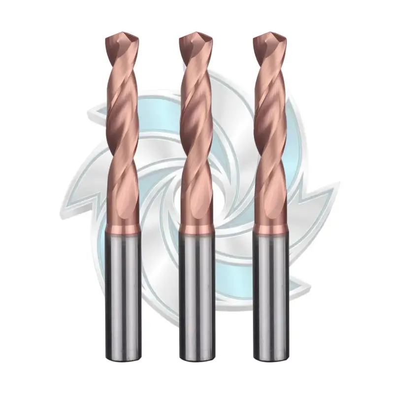
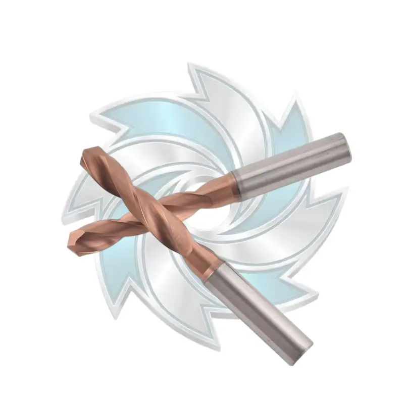
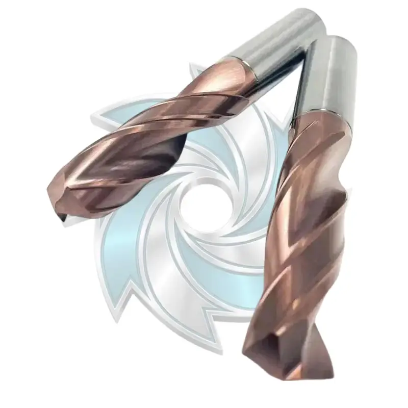
The 5D carbide drill by Durable Mills delivers exceptional centering accuracy and tool rigidity across demanding drilling operations. Engineered for cast iron, stainless steel, and alloy steels, this 5D carbide drill optimizes chip evacuation and heat resistance to increase CNC throughput. Choose our high-precision 5D carbide drill bits for stable hole tolerances and extended production runs.
To prevent solid carbide micro drill breakage, total indicated runout (TIR) must stay under 10% of the drill diameter. For drills under 0.50 mm (0.020 in), your total runout at the flutes should be controlled to 0.002 mm (2 microns / 0.00008 in) or better. Exceeding these limits forces one cutting lip to take all the chip load, leading to rapid fatigue failure and solid carbide micro drill breakage.
Lowering feed rate excessively causes the feed per tooth to fall below the cutting edge radius. When this happens, the tool cannot shear material into clean chips. Instead, it burnishes and rubs the workpiece. This friction work-hardens alloys like stainless steel and titanium, spikes thrust forces, and triggers solid carbide micro drill breakage.
Always use a dedicated stub micro pilot drill rather than a standard 90-degree center drill. The point angle of your pilot must match or exceed your micro drill’s point angle (typically 135 to 140 degrees). Using a 90-degree spot creates an acute cone where the fragile outer corners of your micro drill strike first, causing corner chipping and rapid solid carbide micro drill breakage.
High-precision hydraulic chucks and shrink-fit holders are the best choices for preventing solid carbide micro drill breakage. If you must use ER collet chucks, use only high-end Ultra-Precision (UP) grade collets paired with balanced, bearing-assisted nuts, and verify runout with a high-resolution test indicator before cycling parts.
Eliminating solid carbide micro drill breakage requires combining disciplined shop-floor practices with premium cutting tools. When your job demands tight tolerances and deep aspect ratios in difficult materials, relying on standard drills will only lead to scrapped parts, broken tools, and lost machine hours.
At Durable Mills, we engineer high-performance micro machining tools specifically designed to overcome tool deflection, chip packing, and runout sensitivity. Our Solid Carbide Micro Drill lineup features:
Ready to put an end to chronic solid carbide micro drill breakage and boost your machining uptime?
Our engineering team will review your drawings, cycle setups, and material grades to help you establish the optimal parameters needed to eliminate solid carbide micro drill breakage once and for all.


