
There is a very specific sound every CNC production supervisor dreads hearing during the graveyard shift. It is not the clean, rhythmic hum of a twin-spindle lathe or the steady hiss of high-pressure coolant. It is that sudden, sickening thud—followed by the screech of a servo motor maxing out its torque load, an amber alarm tower flashing, and a three-hundred-dollar tool snapping off flush inside a high-volume transmission hub forging.
When you walk up to the machine enclosure, wipe the mist off the safety glass, and jog the Z-axis back, you already know what you are going to find. The drill body is sheared clean off. The flutes buried in the workpiece look like they were packed with solid cold lead. You do not just have tool wear here; you have suffered a complete mechanical breakdown caused by 5D carbide drill chip packing.
In automated steel production, where cycle times are tuned to the second and robotic part-loaders do not have human intuition, chip evacuation is often the single point of failure. Holes drilled to five times diameter (5xD) represent that exact engineering tipping point where standard evacuation physics break down. Up to 3xD, almost any tool with decent coolant can eject swarf. But once you plunge into the 5D zone in medium-carbon steels like AISI 1045 or tough alloy grades like 4140, swarf friction skyrockets. If your flute volume, fluid hydraulics, and chip geometry do not cooperate, 5D carbide drill chip packing will bring an entire production cell to an abrupt halt.
Let us break down why 5D carbide drill chip packing happens on high-speed CNC transfer lines, look at the counter-intuitive mistakes even veteran machinists make, and lay out actionable shop-floor fixes to keep your spindles turning uninterrupted.
To solve 5D carbide drill chip packing, you have to look at what takes place at the shear zone right where the drill chisel edge and cutting lips engage raw alloy steel. Metal cutting is essentially controlled plastic shear deformation along the material shear plane. As described in classic mechanical models of chip formation, workpiece material flows across the tool rake face, curls under compressive stresses, and breaks into manageable segments.
In shallow depths, chips curl naturally, hit the hole wall, fracture into tight commas or small “C” shapes, and slide out easily. But once a drill penetrates past three diameters down into a blind hole, two destructive physical phenomena take over:
The progression of 5D carbide drill chip packing follows a vicious mechanical cycle:
Shear deformation generates continuous steel ribbon -> Flute friction resists axial evacuation -> Chip column stalls -> Coolant flow is choked off -> Heat spikes to over 900°C -> Chips friction-weld to flute margins -> Spindle torque spikes -> Tool shears off.
When this occurs, operators often blame tool quality. In reality, 5D carbide drill chip packing is almost always an aerodynamic and hydraulic failure caused by mismatching drill flute cross-sections, cutting data, and coolant velocity.
A frequent misstep seen in high-volume production facilities is using general-purpose tools for demanding 5xD automated cycles. A shop will grab tooling designed for 3xD tasks or utility standard twist drills and push them into continuous 5D steel runs. The results are predictable: immediate 5D carbide drill chip packing.
Standard twist drills are usually engineered with a 30-degree helix and a uniform flute cross-section along their entire flute length. That works fine when chips only need to travel 15 mm to 20 mm to escape. But in automated deep-hole production drilling, uniform flutes become choked traffic jams.
Standard Flute Profile vs. Optimized 5D Chip Evacuation Profile
- Standard Drill Design: Constant web thickness down the shank means flute volume remains identical from tip to end. As chips travel upward and bundle together, they encounter increasing friction backup, leading directly to flute choking.
- Optimized 5D Drill Design: Back-tapered core and parabolic flutes ensure the central web thins toward the shank. The available evacuation volume steadily expands as chips move up, preventing jamming.
To permanently stamp out 5D carbide drill chip packing, high-performance tooling utilizes two critical geometric adaptations:
A parabolic flute shape creates a wider, open “U” pocket instead of an abrupt “V” crevice. This open gutter reduces the contact arc between the curled chip and the carbide substrate, drastically cutting evacuation drag. When combined with a dedicated tool like a 5D carbide drill, the swarf maintains a steady upward path without compressing against the flutes.
A rigid core is required to keep a drill from wandering, but a constant thick web chokes flute space. Production-grade drills utilize a tapered web: thicker at the point for compressive rigidity under heavy axial thrust, and thinner toward the shank. This widening space ensures that as steel swarf climbs out of the hole, the available cross-sectional area increases. This simple geometric clearance stops 5D carbide drill chip packing before chips have the chance to wedge.
| Tool Feature | Standard Twist Drill Design | High-Performance 5D Drill Design | Impact on 5D Carbide Drill Chip Packing |
|---|---|---|---|
| Flute Geometry | Standard concave circular flute | Wide-open parabolic trough | Parabolic design prevents chip wedging in flute valleys |
| Web Profile | Uniform web thickness | Tapered web (thicker tip, thinner shank) | Increases evacuation capacity as chips move upward |
| Helix Angle | Fixed 30° standard helix | 25°–32° application-optimized helix | Balances axial chip lift speed and edge strength |
| Margin Width | Double margin full-length | Narrow guide margin or polished single margin | Reduces surface drag and side-wall friction |
| Surface Finish | Ground flutes (unpolished) | Mirror-polished flutes (Ra less than 0.1 µm) | Eliminates micro-burr friction that triggers chip packing |
If your cutting flutes have ground grinding ridges, swarf will grab onto those tiny ridges, slow down, and initiate 5D carbide drill chip packing. Polished flutes act like a non-stick frying pan: hot steel slides out before heat transfer occurs.


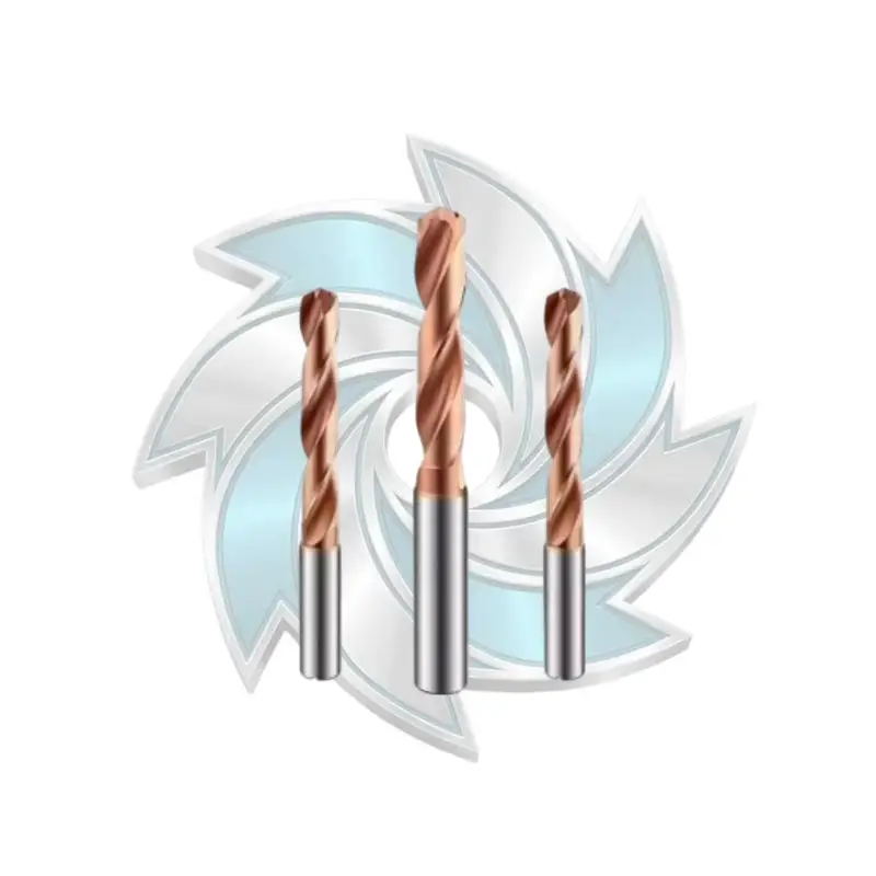
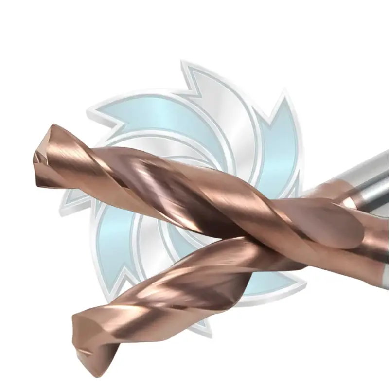
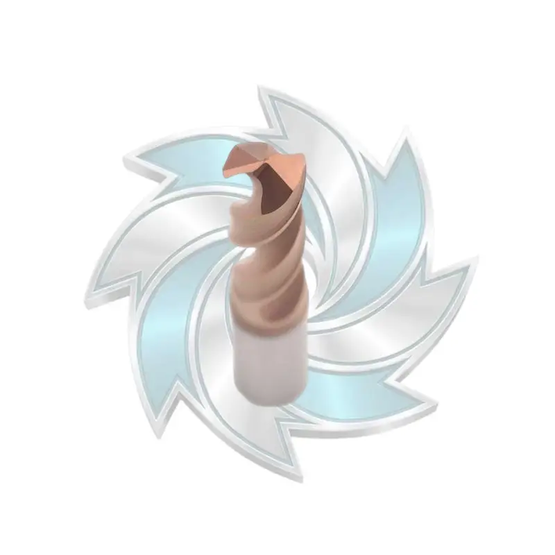
Engineered for precision CNC drilling, our high-performance carbide twist drills deliver exceptional dimensional accuracy across cast iron, structural steel, and stainless steel. Featuring a 140° self-centering point geometry and wear-resistant PVD coating, these industrial carbide twist drills significantly enhance tool life in volume production. Durable Mills supplies premium straight shank carbide twist drills designed to minimize cycle times and machine downtime.
Let us address a major misconception on the machine shop floor: “We have 30 bar coolant pressure, so our chip evacuation must be fine.”
Coolant pressure (measured in PSI or Bar) is merely the force required to push liquid through resistance; it does not tell you if you have enough fluid volume to wash heavy steel swarf out of a bore. To stop 5D carbide drill chip packing, you need both pressure to pierce the air boundary layer of a spinning tool and volume to physically hydro-plane the chips up the flutes.
Industrial fluid applications in machining follow the basic fluid mechanics relationship between flow rate, velocity, and orifice area:
If your tool has micro-diameter coolant ports, your pump gauge might show a sky-high 70 Bar (1000 PSI), but the actual flow delivery inside the hole could be a mere trickle of 6 liters per minute. In deep holes, that trickle boils instantly upon contacting the 800°C primary shear zone. This creates vapor blankets (the Leidenfrost effect), leaving chips dry, glowing, and prone to instant welding. This condition triggers swift 5D carbide drill chip packing.
According to technical specifications defined by the International Organization for Standardization (ISO) regarding machine tool coolant supply, continuous hole cleaning requires tailored flow thresholds based on drill diameter:
| Drill Diameter (mm) | Minimum Through-Spindle Pressure (Bar / PSI) | Recommended Flow Rate (L/min) | Minimum Emulsion Concentration (%) | Risk Level of 5D Carbide Drill Chip Packing |
|---|---|---|---|---|
| 3.0 – 5.0 mm | 50 – 70 Bar (725 – 1015 PSI) | 8 – 12 L/min | 8% – 10% | High (Tight flutes choke rapidly) |
| 5.1 – 8.0 mm | 35 – 50 Bar (500 – 725 PSI) | 12 – 18 L/min | 8% – 10% | High (Requires steady hydraulic lift) |
| 8.1 – 14.0 mm | 25 – 35 Bar (360 – 500 PSI) | 18 – 25 L/min | 7% – 9% | Medium (Sensitive to chip curl shape) |
| 14.1 – 20.0 mm | 20 – 30 Bar (290 – 435 PSI) | 25 – 40 L/min | 7% – 9% | Medium-Low (Needs massive volume) |
Never run a production steel drilling line with weak 4% or 5% emulsion coolant. Lean coolant does not have enough lubricity to drop the friction coefficient between hot steel chips and tungsten carbide. When drilling medium-carbon steels (AISI 1045) or alloy steels (4140, 8620), maintain refractometer readings strictly between 8% and 10%. Proper chemical concentration, as documented in guides on industrial cutting fluid, coats the evacuated chips with an extreme-pressure lubricating film, preventing them from adhering to each other and causing 5D carbide drill chip packing.
When a drill squeals or packs flutes on the night shift, the typical operator reflex is to drop the feed rate override to 80% or 70%.
On a turning or face-milling pass, lowering the feed can nurse a struggling insert through a cut. But in deep-hole drilling with a 5xd solid carbide drill, backing off the feed rate is the worst thing you can do. In fact, running an overly gentle feed rate is one of the most reliable ways to cause severe 5D carbide drill chip packing.
Why does this happen? The answer lies in chip morphology:
Machining parameters should be calculated using standard metal cutting relations:
To keep chip geometry within safe evacuation limits during automated steel production, consult these proven parameter baselines:
| Workpiece Material (Condition) | Hardness (HB) | Cutting Speed Vc (m/min) | Feed fn for 6mm Drill (mm/rev) | Feed fn for 12mm Drill (mm/rev) | Primary Danger for 5D Carbide Drill Chip Packing |
|---|---|---|---|---|---|
| AISI 1020 / Low Carbon | 130 – 160 | 90 – 120 | 0.14 – 0.18 | 0.24 – 0.30 | High ductility creates continuous ribbons |
| AISI 1045 / Medium Carbon | 170 – 210 | 80 – 110 | 0.15 – 0.20 | 0.26 – 0.32 | Built-up edge choking the flute base |
| AISI 4140 / Annealed | 180 – 220 | 75 – 100 | 0.14 – 0.18 | 0.24 – 0.28 | Strain-hardening leading to abrasive swarf wedging |
| AISI 4340 / Quenched & Temp. | 280 – 320 | 50 – 70 | 0.10 – 0.14 | 0.18 – 0.22 | High cutting forces fracturing drill margins |
| 316L Stainless Steel | 160 – 190 | 45 – 65 | 0.08 – 0.12 | 0.14 – 0.18 | Extreme galling causing chips to weld to flutes |
For deeper operational theory on surface speeds and feed balancing across varying machine tool frames, review established engineering guidelines on speeds and feeds.


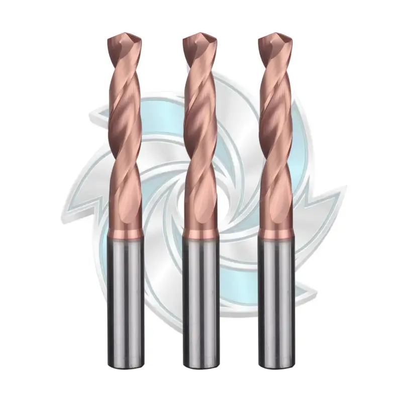
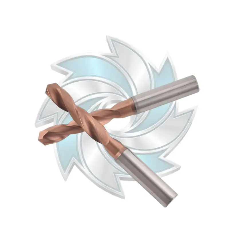
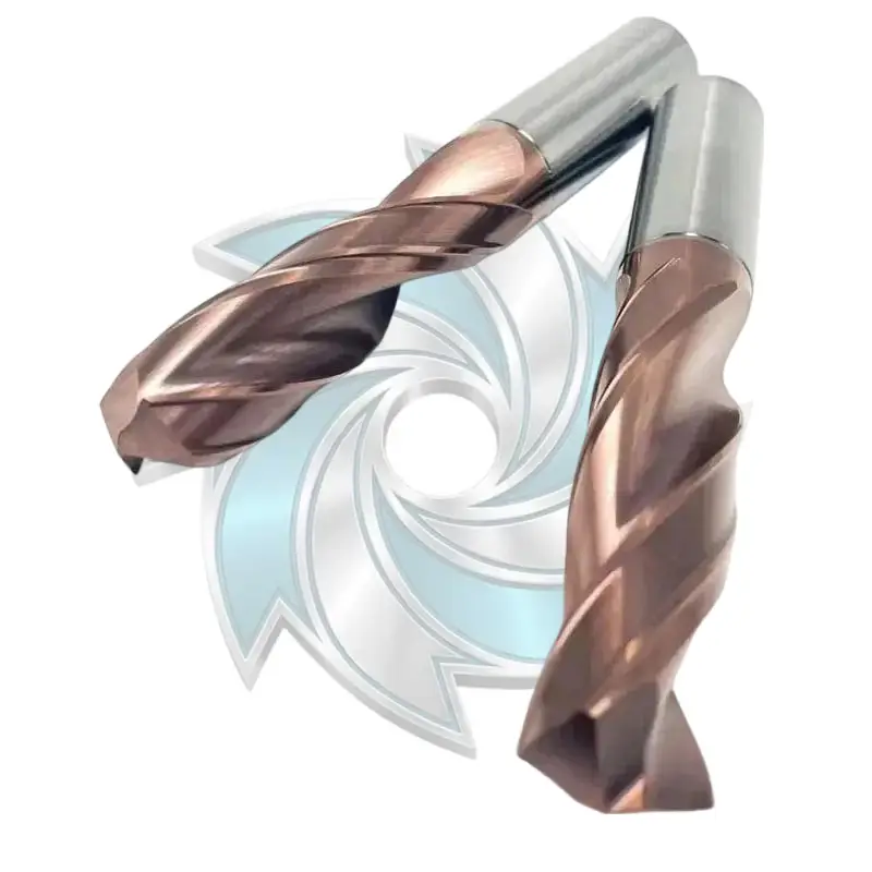
The 5D carbide drill by Durable Mills delivers exceptional centering accuracy and tool rigidity across demanding drilling operations. Engineered for cast iron, stainless steel, and alloy steels, this 5D carbide drill optimizes chip evacuation and heat resistance to increase CNC throughput. Choose our high-precision 5D carbide drill bits for stable hole tolerances and extended production runs.
One of the most persistent shop floor habits is using peck drilling routines (G83 cycles) with modern carbide tools. When an operator runs into 5D carbide drill chip packing, their natural instinct is to reprogram the toolpath with a full-retract peck every 1xD or 2xD.
In High-Speed Steel (HSS) drilling, pecking is standard practice. HSS lacks the rigidity and internal coolant passages required to manage continuous swarf. But when you apply full-retract pecking cycles to a solid cemented carbide drill in automated steel manufacturing, you create new production headaches:
Shop Rule: For 5xD depths in steel, continuous drilling in a single plunge using through-spindle coolant must always be your baseline. Do not use pecking as a band-aid for poor coolant flow or incorrect feeds.
If your machine lacks sufficient coolant pressure to maintain continuous drilling and you absolutely must interrupt the cut to break a chip nest, use a micro-break cycle (dwell or partial chip-break retract of 0.1 mm to 0.5 mm without clearing the hole) rather than pulling the drill completely out of the bore. This chips the ribbon without introducing thermal shock or loose swarf into the bottom of the hole, keeping 5D carbide drill chip packing from occurring.
A Tier-1 automotive component machining facility was running automated horizontal machining center (HMC) cells producing 4140 forged drive-flange components. Each part required eight 10.5 mm through-holes drilled across a 52 mm flange thickness (a depth-to-diameter ratio of nearly 5xD).
The shop was experiencing catastrophic tool explosions every 80 to 140 parts. In every single incident, the drill flutes were fused solid with mangled 4140 swarf—a classic textbook case of 5D carbide drill chip packing. The sudden breakages halted the automated gantry line, damaged hydraulic clamping fixtures, and cost over $18,000 in scraped workpieces and broken tooling in a single month.
When the tooling engineers reviewed the application, they discovered three red flags:
Material Removal Rate (MRR) Calculation & Analysis
General Formula: MRR = (3.1416 * (D / 2)^2) * Vf / 1000
- Baseline Setup: Spindle speed n = 2425 RPM, Feed fn = 0.12 mm/rev, Table feed Vf = 291 mm/min, MRR = 25.2 cm3/min. Generated thin, ductile ribbons that curled back and choked the flute opening.
- Optimized Production Setup: Spindle speed n = 2730 RPM, Feed fn = 0.24 mm/rev, Table feed Vf = 655 mm/min, MRR = 56.7 cm3/min. Yielded tight, self-breaking 3 mm “C” curls that cleared instantly under hydraulic pressure.
The engineering team introduced comprehensive production drilling solutions:
Doubling the feed rate felt counter-intuitive to the operators, who braced for an immediate tool snap. But with the higher feed rate, the 4140 chips thickened, snapped off cleanly into compact 3 mm curls, and shot out of the bore propelled by the 45 Bar coolant blast.
The catastrophic 5D carbide drill chip packing was completely eliminated. Drill life shot up from 120 holes to over 1,400 holes per tool, cycle times per part dropped by 48 seconds, and the automated line ran continuously across three shifts without an unprogrammed alarm.
Carbide drills rarely shatter without warning. Before 5D carbide drill chip packing shears a tool in half, it leaves clear evidence in the chip hopper and across machine telemetry. Training your setup technicians to read chips during regular walk-arounds is the best insurance policy against broken tools.
Reading Your Swarf
- Healthy Chips: Tight, C-shaped or comma curls; uniform straw-tint or natural metallic sheen; dry to lightly wet with clean, sharp edges.
- Warning Indicators: Long nested ribbons; silver feathered fringes; deep purple or blue burned color; crushed and accordion-compressed flakes indicating chip recutting.
Follow this diagnostic matrix to troubleshoot flute choking symptoms before they turn into broken tools:
| Visual Chip Symptom | Underlying Physical Cause | Immediate Danger Level | Corrective Action Required |
|---|---|---|---|
| Chips are deep purple or burnt black | Severe friction; cutting temperature exceeds 850°C; coolant flow restricted | Critical: Imminent 5D carbide drill chip packing | Verify internal coolant ports are unobstructed; raise pump pressure and concentration |
| Long, stringy “bird-nesting” ribbons | Feed rate is too light; chip is too thin to fracture across point geometry | High: Flutes will bind on subsequent plunges | Increase feed rate (fn) by 15% to 25% to force chip breaking |
| Pounded, accordion-compressed chips | Swarf is failing to climb flutes; chips are backing up and recutting | Critical: Tool failure within 1–5 cycles | Check flute finish; swap to polished flutes or high-pressure coolant |
| Built-up edge (BUE) welded on chisel edge | Cutting speed (Vc) is too low; cold welding occurring at core | Moderate: Increases thrust load | Increase spindle speed (RPM); bump coolant lubricity to greater than 8% |
| Spindle load needle creeps up on final 20% of depth | Swarf friction building up as hole reaches 5xD depth | High: Clear sign of early 5D carbide drill chip packing | Reduce margin contact area; adjust back taper; clear backpressure |
Using spindle load monitoring on your CNC control is an effective electronic backstop. Set a Warning Threshold at 15% above nominal drilling load, and an Emergency Spindle Stop at 25% to 30%. When 5D carbide drill chip packing begins at the bottom of a hole, the torque graph curves sharply upward. A properly configured torque limit halts the axis feed before the carbide shatters, saving your workpiece and tool holder.
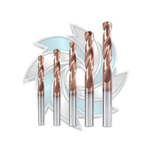


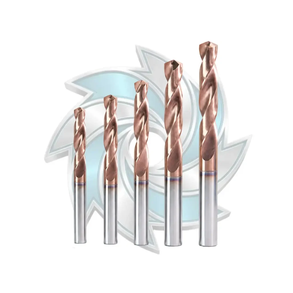
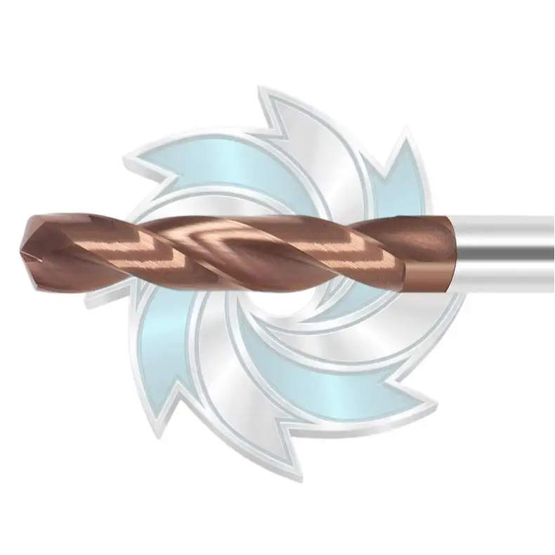
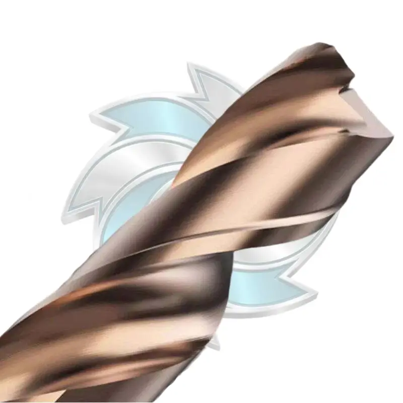
Engineered for high-efficiency holemaking, our solid carbide drill delivers exceptional centering precision across alloy steel and cast iron. This premium solid carbide drill bit features external cooling and an m7 tolerance for smooth chip flow. Choose our solid carbide drills for rigid, high-speed CNC drilling operations.
You can specify the finest tool geometry and high-pressure coolant on the market, but if your drill runout is excessive, you will still fight chronic 5D carbide drill chip packing.
When a drill rotates with high radial runout, one cutting lip takes a heavier chip load than the other. The tool cuts an out-of-round, oversized hole at the entrance, then drifts as it approaches 5xD depth. This misalignment creates asymmetric chips: one flute is starved of material while the other is flooded with oversized swarf. The overloaded flute chokes, leading directly to 5D carbide drill chip packing.
During the first two diameters of drilling (1D to 2D), swarf has an effortless escape path, and chips clear cleanly out of the bore mouth. As the drill penetrates past 4xD toward 5xD, the distance chips must travel expands, and the cumulative friction against the hole wall rises significantly. At the same time, the backpressure of the returning coolant fluid increases, reducing discharge velocity. If your flute volume is constrained, this combination causes swarf to decelerate and accumulate near the bottom of the cut, triggering sudden 5D carbide drill chip packing just before punch-through.
Neat cutting oil provides superior lubricity, which lowers the friction coefficient between sliding chips and flute surfaces. However, oil has a lower specific heat capacity than water-based emulsions and requires substantial pump systems to generate high flow rates without mist fire hazards. In automated mass-production CNC centers, switching to oil is usually unnecessary. Raising a premium water-soluble emulsion concentration to 9%–10% and running through-spindle pressures above 35 Bar typically provides enough lubricity and chip-lifting hydraulic force to prevent 5D carbide drill chip packing without retooling your coolant infrastructure.
Yes, drill point angle directly shapes the chip’s width, thickness, and exit trajectory. A standard 118-degree point angle produces wide, thin chips that are difficult to evacuate through deep flutes. Modern high-performance drills use a 140-degree or 135-degree point angle paired with specialized web thinning. This flatter cutting profile produces a narrower, structurally stiffer chip that curls more tightly into the center of the flute, leaving outer clearance space for coolant to push chips out without causing 5D carbide drill chip packing.
If you are running older CNC machines with lower through-spindle coolant pressures, you cannot safely run continuous full-speed 5D cycles in gummy steels without adjustments. In these cases:
Switch to specialized drills featuring wider parabolic flutes and mirror-polished flute surfaces to lower mechanical resistance.
Reduce cutting speed (Vc) by 15% to 20% to curb thermal expansion in the flutes while keeping your feed rate (fn) firm to ensure chips snap cleanly and do not instigate 5D carbide drill chip packing.
If swarf continues to pack, use a programmed micro-dwell or short chip-break pause (reducing feed to zero for 0.2 seconds every 1.5xD) to snap chip ribbons without retracting the tool from the hole.
Unplanned spindle downtime is the ultimate margin killer in automated steel manufacturing. If your shop floor is continually clearing jammed swarf, dealing with part scrap from seized drills, or battling intermittent tool life across shifts, your process is telling you something: standard tooling cannot withstand the friction profiles of deep production drilling.
At Durable Mills, we engineer reliable cutting performance directly into the steel. Our high-performance 5D carbide drill series is manufactured from ultra-fine grain tungsten carbide substrate, ground with specialized parabolic flute geometries, and mirror-finished to keep steel swarf moving smoothly out of deep bores.
Whether you need to clear tool-choking bottlenecks on an automated automotive component line or require tailored production drilling solutions for high-temperature alloy batches, our technical engineering team can help you review parameters, refine coolant delivery, and eliminate 5D carbide drill chip packing once and for all.
Ready to eliminate catastrophic drill breakages and unlock unattended spindle performance?


